Main Menu
- Home
- Products
- Applications
- Product Support
- Service
- Learn
- About Us
- Contact Us
The Larson Davis Spark® Series multiple dosimeter system usually consists of the 706RC Dosimeter Remote Controller / Sound Level Meter and multiple 703+ or 705+ Personal Noise Dosimeters. NOTE: For the duration of the troubleshooting guide, the text, to avoid duplication, will only refer to the 705+; however the 703+ functions are identical to that of the 705+ and all recommended suggestions apply.
The 706RC has an LCD Display and a keypad for controlling and reading out data from the 705+. Use of these devices to obtain and report worker noise exposure data is usually straightforward and relatively simple, however, as with any system, unusual circumstances may result in actual or perceived fault conditions. The purpose of this document is to help guide you though any anomalous conditions or behaviors which may prevent the proper calibration and use of the system in the field.
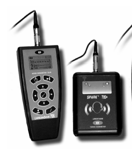
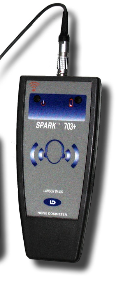
706RC 705+ 703+
The units shown above work together to form a dosimetry system whereby the 705+ personal dosimeter is able to be calibrated, controlled, and viewed by the 706RC remote control unit. This offers the utmost in reliable operation and good sampling results as the subject under test has no controls or display on the dosimeter with which to interfere, nor any visual indication of data to try to influence the results. It also allows the instrument operator to stand a comfortable distance away from the worker while starting / stopping the data gathering, viewing and verifying data, logging status, battery capacity, etc. throughout the day. It is also possible to use the 706RC independently as a simple Sound Level Meter with an optional rigid microphone assembly (MPR002)
Five possible types of failure are covered in this Troubleshooting Guide:
Glossary of Terms used in this Guide:
FOR THE 705+ DOSIMETER:
Sleep Mode: Unit is powered (battery is installed) but unit is not measuring or taking data. This is indicated by a single LED blink every five seconds. The dosimeter is using very little power in this mode and may be shipped / stored while in sleep mode. When a 706RC is present and sending the ‘connect’ signal to the 705+, it will come out of the sleep mode
Power Up Mode: Unit is being powered after having the battery removed for an extended period of time. This is indicated by a simultaneous illumination of both the green status LED and the red power LED. This mode may last from 1 to several seconds depending on the amount of memory which is already being utilized for data storage in the dosimeter.
Awake Mode: Unit has been awakened by the ‘connect’ command issued by the 706RC and is ready for calibration, measurement and calculation of data values.
Connect Mode: Unit is being awakened by the 706RC. This is indicated by a simultaneous illumination of both the green status LED and the red power LED. This mode may last from 1 to several seconds depending on the amount of memory which is already being utilized for data storage in the dosimeter
Running Mode: Unit is measuring noise dose and taking data. Indicated by a fast blink of the green ‘status’ LED
Power Critical Mode: Unit has virtually no battery capacity remaining and cannot perform any function. This is indicated by a single illumination of the red power LED every ten seconds.
FOR THE 706RC REMOTE CONTROL UNIT:
Envelope Icon: Indicates the 706RC is communicating with, controlling and receiving information from the 705+. All information viewed on the 706RC display is coming from the 705+ dosimeter while the envelope display is flashing.
Check Key: The check key is located in the very center of the 706RC keypad and behaves very much like the ‘Enter’ key on your computer. Also, use the check key to acknowledge any message on the display screen which says “OK”
Reset Key: is located in the lower left hand corner of the 706RC keypad; it is used for clearing the overall test results from the display screen. It also behaves like the ‘Esc’ key on your computer, and is a means for reversing to previous menus or display screens
Possible individual faults preventing proper field sampling operations:
1. Unit does not turn on:
Model(s) affected: 706RC
Indicated by: no response when on button is pressed (706RC) no LED has illuminated over a more than 10 second period (705+)
Probable cause: Batteries ‘dead’ or not installed
Recommended fix: Replace Batteries w/ 2 each AA Alkaline cells, by loosening the latch at the top of the battery door and lifting off the cover. Be sure to observe the battery polarity (+ and -) markings in the battery compartment as installing the batteries incorrectly will cause the unit to fail and no longer be operable. If the new batteries do not fix the problem, (and they are known good batteries) then the unit will need to be returned for repair. (Note: do not replace batteries in a Hazardous Location as defined by NFPA code)
2. Unit does not turn on:
Model(s) affected: 705+
Indicated by: No LED has been observed to illuminate over a more than 10 second period (705+)
Probable cause: Battery ‘dead’ or not installed (Note: 703+ uses 2 ea. AA cells)
Recommended fix: Replace Battery w/ 1 each AA Alkaline cell by loosening the screws on the battery cover. Be sure to observe the battery polarity (+ and -) markings in the battery compartment as installing the battery incorrectly will cause the unit to fail and no longer be operable. If the new battery does not fix the problem, (and it is a known good battery) then the unit will need to be returned for repair. (Note: do not replace batteries in a Hazardous Location as defined by NFPA code)
3. Unit (705+) does not connect to 706RC within a few seconds
Model(s) affected: 705+ and 706RC operating together
Indicated by: Display of 706RC reads: “Searching for Any 70x” or “Searching for Serial number 41nnn” (n=some number)
Probable cause: a. Infrared ports are not aligned properly or 706RC is too close or too far away from the 705+ (optimal distance is 1-3 feet) b. battery (ies) are too low in either 705+ (most probable) or 706RC (less probable) to transmit IR signal c. there is interference with other 705+ dosimeters in close proximity d. there is interference with other IR sources or reflection of the IR beam
Recommended fix: a. Try moving the units closer to or farther away from each other. b. replace batteries c. physically relocate other dosimeters, turn them away from the 706RC, place in storage case, etc. d. eliminate other IR sources or shield the 706RC and 705+ from the direct effect of other IR sources. If the units are resting on a highly polished table or a sheet of white paper, reflections from the surface may affect connection or even cause the units to ‘freeze’
4. Unit does not allow Calibration:
Model(s) affected: 705+ Dosimeter
Indicated by: Displayed error message: “Must ▼RESET First OK” (see Fig.1)
Probable cause: Dosimeter must be reset before Calibration can take place
Recommended fix: Press ‘Check’ key to erase error message, then press reset key three times until you see “▼ Reset Overall? YES NO” Press Check key once, then ‘tools’ key to return to Calibrate screen. Proceed with Calibration as normal. NOTE: If dosimeter does not respond or appears to be reset, yet will still not allow Calibration, see 7. below
5. Unit does not allow Calibration:
Model(s) affected: 705+ Dosimeter
Indicated by: Displayed error: “Must ► STOP and ▼RESET First OK”
Probable cause: Dosimeter must be stopped (from taking data) and reset before Calibration can take place.
Recommended fix: Press ‘Check’ key to erase error message, then press RUN key once, then press RESET key three times until you see “▼ Reset Overall? YES NO” Press Check key once, then press the TOOLS key to return to Calibrate screen. Proceed with Calibration as normal.
6. Unit does not Calibrate / Calibration fails:
Model(s) affected: 705+ Dosimeter
Indicated by: ! in upper left hand corner of display on calibrate screen when connected to the 706RC. (This will also be seen in the lower part of the display accompanied by the word “LOW”. See 4. for normal Calibration process)
Probable cause: a. Calibrator is not turned on, b. microphone is not placed in the opening of the calibrator, c. calibrator output is incorrectly selected, or d. microphone not connected or is malfunctioning.
Recommended fix: a. Press round ‘ON’ button on side of CAL150 calibrator to turn it on. (see Fig 2). Note: calibrator will turn itself off after 90 seconds in order to save battery power. If calibrating multiple dosimeters, it may be necessary to press the on button again) b. Make sure the microphone is firmly placed into the opening if the calibrator adapter; there is an “O-ring” seal in the inner diameter of the calibrator adapter and this may require firm force to seat the microphone all the way into the adapter opening. c. There is a miniature slide switch on the calibrator housing (the same side of the case as the ON button). Make sure this ‘dB Level’ switch is in the “114 dB” position (pushed all the way towards the end of the calibrator which has the microphone opening. d. Make sure the silver microphone connector is fully seated in the mating receptacle in the top of the dosimeter. If it is fully connected and still indicating ! or ! LOW on the calibration screen, then the microphone is most likely defective and should not be used. To verify this, take a different microphone and substitute it for the malfunctioning and proceed with calibration procedure. If the calibration is successful then it is the first microphone which is at fault.
7. Unit appears ‘frozen’ and does not respond to commands
Model(s) affected: 705+ Dosimeter
Indicated by: Display prompt on 706RC is asking the operator to “first Stop and Reset” even though 705+ dosimeter is not running / no data are present.
Probable Cause: Unit has had some interference and/or interruption of infrared control most likely caused by having multiple dosimeters in close proximity to each other while attempting communication or control by the 706RC.
Recommended fix: Remove the battery from the dosimeter and set it aside for at least five minutes, then replace the battery and observe the dosimeter as it indicates it is going through the Power Up mode (see Glossary). This action will perform a complete system reset of the dosimeter – NOTE: you must check the date and time and reset it if has been changed back to the default settings (1/1/08 and 00:00:00) due to loss of power.
8. Battery Capacity insufficient for full shift monitoring:
Model(s) affected: 705+ Dosimeter
Indicated by: trouble connecting; sluggish response, Red battery indicator LED is illuminating once or twice every three seconds; red LED is illuminating once every ten seconds; no LED has illuminated over more than a 10 second period
Probable cause: Battery almost ‘dead’ or ‘dead’
Recommended fix: Replace the battery with a known good battery. (Note: do not replace batteries in a Hazardous Location as defined by NFPA code)
9. Unit does not display correct date or time:
Model(s) affected: 705+ Dosimeter
Indicated by: displays incorrect date and time
Probable Cause: battery is ‘dead’ or has been removed from dosimeter for a period of time
Recommended fix: Reprogram correct date and time by using 706RC to enter correct date and time manually or connect 705+ dosimeter to the PC using Blaze software. (Once connected, the Blaze s/w will automatically synchronize the date and time to the settings of the PC)
10. Unit displays ‘Mic Fault’
Model(s) affected: 705+ Dosimeter and 706RC
Indicated by: displayed error message: “MIC FAULT OK”
Probable Cause: a. microphone is not connected b. microphone was unplugged by the worker during the test and plugged back in c. microphone is malfunctioning
Recommended fix: a. plug in microphone, press ‘Check’ key to erase error message. (Note: alarm bell indicator will remain on the display to let you know this unit had experienced a mic fault) b. press ‘Check’ key to erase error message. c. substitute a different microphone and recalibrate before further use
Illustrations referred to in this Guide:
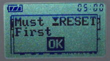
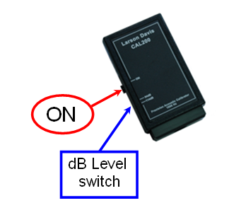
Fig. 1: “Must ▼RESET” message FIG. 2: Calibtrator Controls
Leave a commentOrder by
Newest on top Oldest on top