Main Menu
- Home
- Products
- Applications
- Product Support
- Service
- Learn
- About Us
- Contact Us
The 426A12 can output signals that could potentially damage the input circuitry of the 820, 824 or 870 sound level meter. To correctly interface these SLM’s to the 426A12 use the additional equipment listed in Table 1. See Figure 1 and Table 2 for additional information on the connections.
Table 1. Additional Equipment Required for Connection to 426A12
Notes:
1Connecting additional preamp and ADP006 directly into SLM signal connector may be too tall for NMS box. Using CBL078 or CBL092 short extension cable makes the connections possible and also allows fit inside NMS box.
2 Cable has default length of 20 feet. Custom lengths are also available.
3 If 426A12 is directly replacing a PRM2100K or PRM2101K a 426A12-NPT adaptor pipe coupler will be required.

Figure 1. Block diagram of interconnections
Table 2. Control Cables Used
4 An optional adapter cable, S2175.03, is available to connect the CBL197 control cable to a Larson Davis outdoor monitoring system that has a power and ground block system (see Figure 1 for additional information).
Will the 426A12 mount directly to an existing pole that previously had a PRM2100K or PRM2101K mounted to it?
The PRM2100K and PRM2101K both use a 1.5”-11.5 NPT mounting thread, whereas the 426A12 uses an ISO 228-1 G 1.5” mounting thread. The 426A12-NPT adapter pipe coupler is available to convert the 1.5” NPT to the required ISO 228-1 G 1.5” thread, allowing the mounting of the 426A12 to the original pole.
What 426A12 features are available when used with the Model 820, 824, or 870 SLM?
The following features of the 426A12 are available when used with the Model 820, 824, or 870 SLM:
The following features of the 426A12 are not available when used with the Model 820, 824, and 870 SLM’s:
How does the additional in-line preamp affect the performance of the system?
The additional in-line microphone preamplifier (PMR828, PRM902, or PRM900) does slightly change the dynamic range and noise floor relative to the original outdoor system. Listed below are typical results, comparing the PRM2100K and PRM2101K outdoor microphone preamplifiers to the 426A12 configured with the additional equipment listed in Table 1.
All of the test are performed with a 12 pF equivalent microphone capacitance at the front end of the outdoor microphone preamplifier. The ADP006 (47 pF) adapter at the input of the PRM828, PRM902, or PRM900 has negligible effect to the noise floor and frequency response of the system.
This FAQ outlines the procedure for using Blaze Demo to update HVM100 firmware to version 1.33.
Required Items
Warnings
Instructions
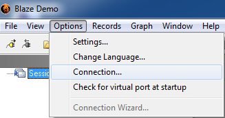
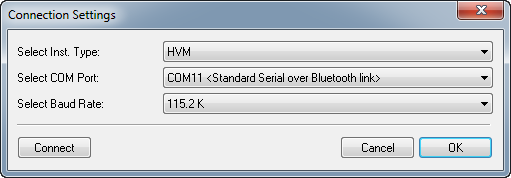
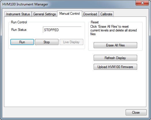
5. In the HVM100 instrument manager, select Manual Control then Upload HVM100 Firmware which will start the firmware upgrade program.
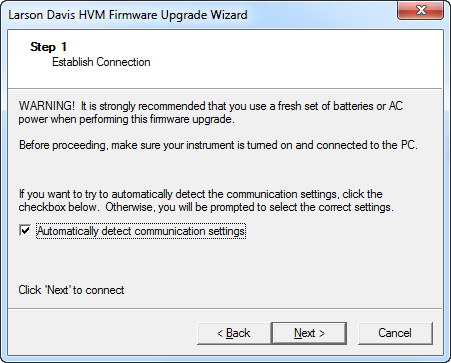
6. On the first dialog, select Next
7. On the second dialog, check automatically detect communication settings
8. If the HVM100 is found, a menu with language options will appear. If the HVM100 is not found, verify the CBL006 is connected and the assigned COM port is less than COM14.
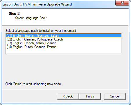
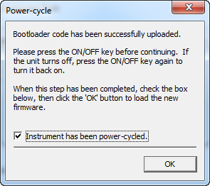
9. Select the desired language set and the Finish. The HVM100 will begin to reprogram the firmware and ask you to turn the HVM100 off then back on. Once this is completed, check the box and select OK
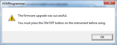
10. Once the message below has been displayed the firmware upload is complete and by pressing the on/off button the HVM100 will resume normal operation.
Please follow the instructions below to upgrade the System 824 firmware. Before
applying this procedure you will need to obtain the firmware file (ld8-xxxx.rom) and
authorization file (824-xxxx.ldk), by contacting Larson Davis technical support at contact
information listed in the footer of this page.
Initial Setup
1. Power down the computer and the 824.
2. Connect an available RS-232 serial port on the PC to the 824 via CBL006 cable.
3. Turn the computer on, then the 824.
4. On the 824, press Setup, select SLM ISM, then press the checkmark. Then press TOOLS, and select Communication, then press the checkmark, and set the baud rate to 9600.
5) .Start the 824-Utility software v3.12 on your PC.
Connecting
1. Under the software’s File menu, select 
Connect or press the tool bar icon.
2. Enter the COM port, and 9600 Baud Rate of your 824. Press Connect.
3. Your instrument will connect and its serial number and revision will appear on the
Title tab window.
Upgrading Firmware
1. Under the File menu, select 
Upgrade…,then browse to your 824-xxxx.ldk file.
2. Put a check mark in the Apply Firmware box, and press Start. The upgrade will take a few
minutes.
CAUTION: DO NOT DISCONNECT
during the process.
3. Once the upgrade is complete, verify that the 824 has a new revision in the TOOLS,
About-a screen shown below.

4. If you purchased new options, you may either select both the firmware upgrade and
options upgrade boxes or repeat the procedure, selecting Apply Options in step
2 above. The Apply Options function will only take a few seconds.
Contact Larson Davis Customer Service at techsupport@larsondavis.com or (888) 258-
3222 if you have any questions regarding your upgrade.
Using the AC/DC out from the Model 831 or SoundTrack LxT you can convert the DC signal to a 4-20mA signal using the IMI 682A06 Universal Transmitter, with optional display 070A80.


The setup requires the following:


Complete setup

The 682A06 allows for a 2-point calibration, via the ADV SET » CAL » CAL LO / CAL HI / USE CAL screens.
The reason is due to the fact that what you are calculating when you sum the values of the 1/1 and 1/3 Octave bands is not an overall level. This number is simply the summed level of the 1/1 or 1/3 octave bands. This is best characterized in the plot below:

This means that when adding up the 1/1 and 1/3 octave bands, the frequencies at or around the cutoff frequencies of the filters will have a slight error. This is why these numbers can not be used to accurately calculate the overall sound pressure level. Even more error is seen when performing a Weighting after Filtering, as seen below.
When applying weighting curves via postprocessing, the attenuation at the cutoffs of the Octave Filters in addition to another factor can cause even greater error. As an example, applying the attenuations of an A weight filter by hand will not likely yield the same results as running the raw data through a filter, and calculating the overall level. The plot below shows the error on these calculations:

So if a frequency is close to the cutoff, the attenuation applied by simply subtracting it from the 1/1 or 1/3 octave band may be off by as much as 15 dB off. This creates an even larger difference between the Overall Level and the 1/1 and 1/3 Octave Sum.
Overview: Connect a Model 831 to an underwater hydrophone.
Features : Model 831 Measures underwater noise.
The 831 can connect to a piezoelectric hydrophone -
Note: When using the RA0043 hydrophone adaptor with a pistonphone, the volume is changed slightly and therefore a hydrophone calibration adapter correction factor should be applied. The calibration factor can be found on the RA0043 calibration chart or is etched on each adapter.
Note: the K-Factor can also be verified in the field by using the 1/2" sampling port on the side of the adapter.

Example: To calibrate using a standard 114 dB pistonphone such as GRAS 42AA, enter 144.5 dB:
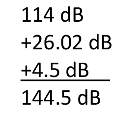 use actual sensitivity from calibration sheet to change reference pressure from 20 μPa in air to 1 μPa for water K-Factor, correction for volume difference when using RA0045 Sensitivity to enter in 831 when calibrating TC4013 hydrophone
Required Hardware and Firmware for listed Features
Brief Feature Description
If SLM Utility G4 (any version) or SLM Utility G3 version 2.300 or later is unable to connect to a sound level meter, there are two potential causes.
Cause #1 – The USB driver for the Model 831 or LxT sound level meter is not correct

On a Windows 8 PC
2. Using a USB cable, connect the sound level meter to the computer making sure the meter is powered on and fully booted.
3. In the list of devices, find the item Larson Davis USB device and expand the list to show the device

4. On the device Larson Davis Model 831 & SoundTrack LxT, right click and select Properties

5. On the properties page, the driver manufacturer should be libusb 1.0

6. If the driver manufacturer is “libusb 1.0” and you cannot connect then proceed to Cause #2. If the driver something different like motusb.dll then uninstall the SLM Utility G3 and/or G4 software then reinstall. Make sure that you install by running LDsetup.exe and that you have administrator rights.
Cause #2 – The USB hardware driver needs an update
This problem only occurs when using a USB 3.0 port with drivers from certain hardware manufacturers.
7. Verify that connected port is USB 3.0. This can be done one of two ways

b. Within device manager, expand the Universal Serial Bus Control and look for a port name that includes Renesas Electronics USB 3.0 in the name

8. If there is a Renesas Electronics USB 3.0 device or device manager shows a device that is unknown and doesn’t have a driver, the USB 3.0 driver needs to be updated. This driver is provided by the manufacturer of the PC or motherboard. Normally, you can find the driver with instruction for updating if you google the manufacturer and model of the PC + USB 3.0 driver. For example, I would google Lenovo T420s USB 3.0 driver.
9. Follow the manufacturer’s instructions for updating the driver and you should now be able to connect. If a workaround is needed, any available USB 2.0 port will work.
There are in principle two ways to use DNA for RT60. Both options require the DNA option for building acoustics, SWW-DNA-BA, and Model 831 driver, SWW-DNA-831.
Both methods will give you access to the RT60 display / menu, shown below.

This window allows you to:
- View RT20, RT30, or RT15 data.
- See the spectrum
- Delete a decay
- Translate data for import into DNA for analysis and graphing
Importing data from 831-RT (DNA will recalculate RT15, 20, 30 based on recorded decays)
- Make and store an RT60 measurement on the Model 831.
- Start DNA, connect to the 831, (Analyzer, 831, then click the connect icon).
- In DNA831 analyzer window:
- You can toggle the RT60 window, on or off using the RT60  menu button
Viewing RT60 data in DNA
- In the RT60 window, select Options, and put a checkmark in Schroeder Backward Integration and Use Ensemble averaging between positions, then click OK.

- You can save the data in an RTdat file (RT60 Measurement -> Save as from the main menu) and reload later.
- Click Export to doc, select if you want to export all decays, click OK, then you can include your measurement info and click OK. The data will be translated to the DNA document window.
NOTE: You can switch the 831 from RT60 mode to SLM mode using the DNA DirectScreen option in the View drop-down menu. It is recommended to disconnect and reconnect the 831.
Measuring RT60 with DNA and the 831
- Start a new measurement with (RT60 Measurement -> New)
- Turn above display on using RT60 icon 
- Push Run and use the Accept/Reject buttons until you Stop
- The Run/Stop acts as position increment just like Start/Stop does on 831.
Translating the RT60 data to DNA for reporting
There are 2 ways here too:
1) Via the graph above using the Export to doc button
2) Or via the RT Measurement -> Translate RT60 menu
The 3 template options are: RT60 spectrum only
RT60 spectrum with multi-column table (best for 1/3rd octave)
RT60 spectrum with single column table (best for 1/1 octave)

See DNA-BA Architectural Acoustics to further tune the RT results in DNA
Rush Service Orders Option
Applicable products: ALL service orders (CER-xxx)
CER-RUSH gives you top priority for service orders
Type 2 Adapter for circumaural earphones
You need the AEC201-2 Type 2 adaptor for circumaural earphones only for KOSS HV/1A type earphones.
The Type-2 adapter is the flat crenellated adapter plate converting the Acoustic Coupler for use with Circumaural Earphones. This adapter is mentioned in ANSI S3.6 (2010) and in ISO 389-5 for use with the KOSS HV/1A earphones.
From ANSI S3.6 (2010) we have the following:


The IEC 60318-1 (2009) no longer mentions the crenellated Type 2 adapter. (IEC 60128-1 and IEC 60318-2 have been merged into IEC 60318-1(2009).) ISO 389-5 for the HF RETSPL in Annex B shows again the crenellated adapter for KOSS HV/1A

Larson Davis instrumentation is used in community and environmental noise monitoring, measurement of building acoustics, managing worker exposure to noise and vibration, and various automotive, aerospace, and industrial applications. Larson Davis is a division of PCB Piezotronics, Inc., a wholly owned subsidiary of Amphenol Corporation.
Full About Us
Subscribe to our newsletter for the latest technical news, training opportunities, & product updates from Larson Davis.
| SensorlineSM | |
| Sales and Technical: |
3425 Walden Ave
Depew, NY 14043 USA
SensorlineSM
716.684.0001
Email Sales Support
Email Technical Support
Sales and Technical:
716.926.8243
Cookie Preferences | Privacy Policy | Factory Calibration | Equipment Rental | Product Repair | Amphenol Human Trafficking and Slavery Statement | CA Prop 65 Warning
© PCB Piezotronics, Inc. In the interest of constant product improvement, specifications are subject to change without notice. PCB®, ICP®, Swiveler®, Modally Tuned®, and IMI® with associated logo, SoundTrack LxT®, SoundExpert®, and Digiducer® are registered trademarks of PCB Piezotronics, Inc. in the United States. ICP® is a registered trademark of PCB Piezotronics Europe GmbH in Germany and other countries. SensorLine℠ is a service mark of PCB Piezotronics, Inc.